Introduction to Ethernet
Follow the physical link and the Ethernet frame separately, then use interface evidence to identify a simple link failure.
Independent lab examples; selected output and frame summaries are illustrative. Port naming and command support vary by switch and software release.
Choose the link technology
Ethernet covers a family of physical link technologies and a shared MAC framing model. A switch can connect a host on a copper access link to a server reached through a fiber uplink. Each segment must use compatible interfaces, optics, media and supported speed settings; forwarding between segments does not make incompatible physical interfaces interoperable.
| Medium | What to verify |
|---|---|
| Twisted-pair copper | Supported category, connector, pair integrity, speed and distance; common 1000BASE-T channels allow up to 100 m under their cabling specification. |
| Fiber | Matching optical standard, wavelength, fiber type, reach and transmit/receive polarity; connector shape alone is insufficient. |
| Pluggable transceiver | Both switch support and remote-end optical compatibility; supported modules differ by platform. |
Legacy 10/100BASE-T wiring distinguished straight-through and crossover connections. Auto-MDI/MDIX can correct pair orientation when supported and enabled. 1000BASE-T uses all four pairs. Auto-MDI/MDIX is not the same as speed/duplex negotiation and cannot repair a broken conductor.
Agree speed and duplex
Half-duplex Ethernet shares access to a medium and uses collision detection and backoff. A modern point-to-point full-duplex link can send and receive simultaneously and does not use CSMA/CD. This is distinct from wireless medium access.
Use compatible settings at both ends. Automatic negotiation is the normal starting point on supported copper access interfaces. Forcing only one end on some older 10/100 links can leave a duplex mismatch. Supported commands and negotiation behavior differ for copper, fiber and speed; do not force a generic setting on every platform.
Read an untagged Ethernet II frame
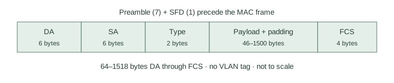
| Field | Meaning |
|---|---|
| Destination address (DA) | Six-byte receiver address used in the forwarding decision. |
| Source address (SA) | Six-byte sender address that a learning switch associates with the ingress port and VLAN. |
| EtherType | Two bytes identifying the payload protocol; for example 0x0800 IPv4, 0x0806 ARP and 0x86DD IPv6. |
| Data and padding | Carries the payload; padding satisfies the minimum frame size when required. |
| FCS | Four-byte cyclic redundancy check for detecting corruption; it does not authenticate the sender. |
Destination through FCS is normally 64–1518 bytes for the untagged frame, with 46–1500 payload/padding bytes. Preamble, start delimiter and interpacket gap are not included in that MAC-frame length. The ordinary 1500-byte IP MTU excludes the Ethernet header and FCS. A capture adapter may remove the FCS before software receives the record.
Recognize the address, not just its spelling
A MAC address is 48 bits. The forms 0200.0000.0011 and 02:00:00:00:00:11 represent the same value. These examples are locally administered unicast addresses, not vendor identifiers. Addresses can be assigned by software and must be managed to avoid duplicates; they are not guaranteed to be permanently unique.
The broadcast destination is ff:ff:ff:ff:ff:ff. A unicast destination identifies one intended receiver; a group address can identify multiple receivers. An Ethernet II type value identifies the encapsulated protocol, not the outgoing interface. The older length/LLC encapsulation has different interpretation; the two-byte field is not always an EtherType.
Inspect a concrete frame and port
Use the clean SW1/H1/H2 VLAN 10 recipe from Introduction to LAN, independently of previous forwarding-table contents. This reconstructed frame summary represents H1 sending an IPv4 packet to H2 after address resolution has succeeded. It is not a recorded capture.
Ethernet II
  Destination: 02:00:00:00:00:12
  Source:      02:00:00:00:00:11
  Type:        IPv4 (0x0800)
IPv4
  Source:      10.10.10.11
Destination: 10.10.10.12SW1#show interfaces GigabitEthernet1/0/1
GigabitEthernet1/0/1 is up, line protocol is up (connected)
MTU 1500 bytes, BW 1000000 Kbit/sec
Full-duplex, 1000Mb/s, media type is 10/100/1000BaseTX
0 input errors, 0 CRC, 0 frame, 0 overrun, 0 ignoredRead negotiated speed and duplex alongside the host NIC state. Compare error-counter changes during a known test; a zero or nonzero cumulative counter by itself does not prove the present cause. FCS detects damage but neither identifies its exact location nor repairs the frame.
Repair an administratively disabled port
SW1#show interfaces GigabitEthernet1/0/1
GigabitEthernet1/0/1 is administratively down, line protocol is down (disabled)
For this isolated fault, SW1 has shutdown configured while the host, cable and VLAN are healthy. Re-enable only the intended lab port.
configure terminal
interface GigabitEthernet1/0/1
 no shutdown
endSW1#show interfaces status
Port Name Status Vlan Duplex Speed Type
Gi1/0/1 connected 10 a-full a-1000 10/100/1000BaseTXThe link is restored in this example. If it remains notconnect, investigate the remote NIC, cable and compatible media; if err-disabled, find the protection cause instead of repeatedly re-enabling it.
Further reading
Key Takeaways
- Physical compatibility and logical frame interpretation are separate checks.
- Full-duplex Ethernet sends and receives simultaneously without CSMA/CD.
- An ordinary untagged MAC frame is 64–1518 bytes including FCS, excluding preamble and SFD.
- Source and destination MAC addresses have different roles; EtherType describes the payload.
- Check actual port state, negotiated mode and counter changes before choosing a repair.