Chassis aggregation
Separate supervisor redundancy from redundancy across whole chassis.
Independent lab examples; selected output and frame summaries are illustrative. Port naming and command support vary by switch and software release.
Network and objective
Architectural lesson using legacy VSS-capable chassis as an example; modern StackWise Virtual and other systems have their own guides.
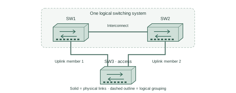
SW1 and SW2 represent distribution chassis. Each contains supervisors, line cards, and power supplies. SW3 is dual-homed to them, so the design must survive more than one individual line-card failure.
How it works
Two supervisors in one chassis protect selected control-plane failures, but they share parts of the enclosure and infrastructure. A second chassis adds another physical location for forwarding resources. Independent power feeds and link placement are still necessary.
A virtual switching link carries synchronization and traffic that must cross between chassis. Put its members on suitable separate modules when the platform supports that design, and size it for traffic during failures rather than just its steady-state load.
A multi-chassis EtherChannel can use one member on each chassis. Local forwarding can reduce interconnect traffic, but traffic toward a port on the other chassis still needs the interconnect. Loss of that interconnect must invoke a defined dual-active recovery mechanism.
Configure or inspect
No feature change is required for this conceptual comparison. Inspect the operational state below on an isolated compatible lab platform.
Verify the result
Design evidence (conceptual)
Physical chassis: 2
Logical aggregation partner: 1
Access uplink: one member per chassis
Independent checks: supervisor, line card, power, interconnect
The diagram describes fault domains rather than a universal configuration recipe. Verify the exact chassis, supervisor, line-card, software, and optics combination before selecting the virtualization method.
Failure and recovery
Both interconnect links are installed on one line card. A single card failure removes the entire synchronization path even though two cables exist.
Redesign the interconnect across supported independent modules and provide the documented dual-active detection path. Validate the resulting failure matrix during a maintenance lab, including whole-chassis loss.
Further reading
Key Takeaways
- Supervisor redundancy is not chassis redundancy.
- Place links across suitable fault domains.
- Interconnect capacity matters during failures.
- MEC spans coordinated chassis.
- Dual-active recovery must be designed.