RSTP configuration
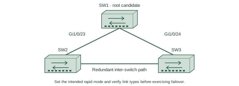
Set the intended rapid mode and verify link types before exercising failover.
Independent lab examples; selected output and frame summaries are illustrative. Port naming and command support vary by switch and software release.
Network and objective
Rapid-PVST+ is scoped to supported switches. The independent baseline uses full-duplex Gigabit transit links.
Use three fresh isolated switches with Gigabit trunks: SW1 Gi1/0/23 ↔ SW2 Gi1/0/23; SW1 Gi1/0/24 ↔ SW3 Gi1/0/24; SW2 Gi1/0/24 ↔ SW3 Gi1/0/23. Both VLANs10/20 exist on every switch. Baseline SW1/SW2/SW3 priorities are4096/8192/12288, with short costs and no extra links. Start independently from the included baseline for each lesson; subsequent repair snippets apply to the named device.
How it works
Configure compatible rapid mode deliberately on the three-switch lab and retain the explicit root priorities. An inter-switch point-to-point link is not a host edge. Full-duplex operation commonly supplies point-to-point classification, which can also be overridden on supported platforms.
Add edge behavior only on SW3’s actual host access interface. Test direct root-port loss, inspect alternate promotion and restore the link. The elected topology after recovery depends on normal cost/identity rules, not on which cable was restored last.
Configure or inspect
SW1
vlan 10
vlan 20
spanning-tree mode rapid-pvst
spanning-tree pathcost method short
spanning-tree vlan 10 priority 4096
spanning-tree vlan 20 priority 4096
interface range GigabitEthernet1/0/23 - 24
 switchport mode trunk
 switchport trunk allowed vlan 10,20
 switchport nonegotiate
 no shutdown
exit
SW2
vlan 10
vlan 20
spanning-tree mode rapid-pvst
spanning-tree pathcost method short
spanning-tree vlan 10 priority 8192
spanning-tree vlan 20 priority 8192
interface range GigabitEthernet1/0/23 - 24
 switchport mode trunk
 switchport trunk allowed vlan 10,20
 switchport nonegotiate
 no shutdown
exit
SW3
vlan 10
vlan 20
spanning-tree mode rapid-pvst
spanning-tree pathcost method short
spanning-tree vlan 10 priority 12288
spanning-tree vlan 20 priority 12288
interface range GigabitEthernet1/0/23 - 24
 switchport mode trunk
 switchport trunk allowed vlan 10,20
 switchport nonegotiate
 no shutdown
exit
interface GigabitEthernet1/0/1
 switchport mode access
 switchport access vlan 10
 spanning-tree portfast
 no shutdown
Verify the result
SW3#show spanning-tree summary
Switch is in rapid-pvst mode
SW3#show spanning-tree vlan 10
Gi1/0/24  Root FWD 4 128.24 P2p
Gi1/0/23  Altn BLK 4 128.23 P2p
Gi1/0/1   Desg FWD 4 128.1  P2p Edge
The two uplinks are transit links and the actual host is edge. Preserve this distinction during tests rather than marking every interface PortFast.
Failure and recovery
If the expected alternate does not activate after a controlled failure, check VLAN carriage, link status, inconsistency protections and received BPDUs. Timer changes are not a substitute for an eligible backup path.
SW3
interface GigabitEthernet1/0/24
 shutdown
end
show spanning-tree vlan 10
configure terminal
interface GigabitEthernet1/0/24
 no shutdown
Further reading
Key Takeaways
- Select the intended rapid mode explicitly.
- Keep root placement deliberate.
- Transit and edge roles are different.
- Failover requires an eligible alternative.
- Restore the failed link and verify normal selection again.