Sensor placement and visibility
Choose a sensor location by the traffic you need to see, then prove the actual observation boundary.
Examples target Suricata 8.0.1 on a prepared Linux lab host. Constructed outputs are illustrative, not live sensor results. Commands are lesson examples; no sensor or enforcement is started by this page.
Start with a visibility question
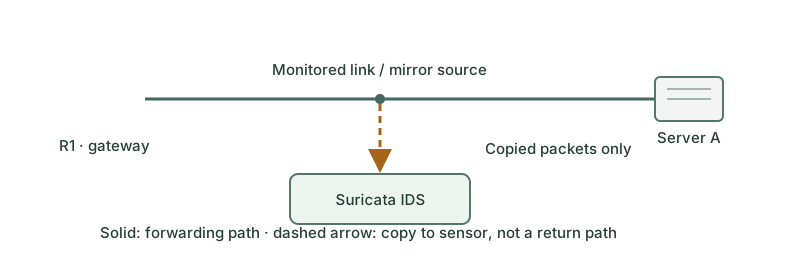
Suppose users in 10.10.10.0/24 reach a public service through R1, while Server A and Server B exchange data on one internal switch. A sensor on the R1 uplink can see traffic that crosses that uplink. It does not automatically see the two servers talking locally. The first design question is which conversations must be observable.
Compare candidate locations
| Location | Useful view | Important blind spot |
|---|---|---|
| Outside the perimeter firewall | Traffic arriving before perimeter filtering | Internal east–west flows and original private identity after NAT |
| Inside the perimeter | Traffic permitted toward internal systems | Traffic already discarded outside and local flows elsewhere |
| DMZ or server segment | Traffic to protected service networks | Other VLANs and switched traffic not mirrored |
| Virtual switch or workload boundary | Selected virtual-machine or container flows | Other hosts, overlays and unselected virtual ports |
One location rarely covers every requirement. Use a small coverage map before adding sensors. More copies can create duplicates or overload; more devices also create correlation and maintenance work.
Deliver the right packet copy
A SPAN/mirror session must select the relevant ports or VLANs and directions. A TAP provides a physical observation feed, but its output and aggregation still need suitable capture interfaces. Oversubscribing a mirror destination can lose packets even when the sensor reports a low local capture-drop count.
Preserve both directions of each conversation at the same analysis point where practical. Check VLAN tags, link encapsulation, tunnel handling and timestamp quality. An outer tunnel view is not equivalent to a view after decapsulation; confirm supported decoding for the traffic actually delivered.
NAT and encryption change the evidence
Before source NAT, a sensor can observe the original client address; after NAT it may see only a shared translated identity. Correlate NAT or proxy logs when investigating across those boundaries. HOME_NET classifies addresses for rules; it does not steer traffic into the sensor or recover identities hidden by translation.
TLS and other encryption can leave useful connection metadata while hiding application content. Placement after an authorized decryption boundary may change visibility, but does not mean every protocol or field becomes available. Suricata itself is not a general TLS decryption service.
Validate coverage with a traffic matrix
| Known benign test | Perimeter uplink sensor | Server-segment sensor |
|---|---|---|
| Client → external service | Expected if selected on that uplink | Only if the client path also crosses that segment |
| Server A → Server B on one switch | Not expected on the perimeter uplink | Expected only if the relevant switching traffic is copied |
| Alternate-path return traffic | Missing unless that path is also covered | Depends on its route and mirror scope |
For each test, compare packet/byte direction counts with flow or protocol records and an endpoint observation. Record what is absent by design. Check switch/TAP counters as well as sensor capture and decoder statistics. A successful ping verifies connectivity, not complete detection coverage.
Revisit placement after routing, VLAN, overlay, NAT or TLS architecture changes. Keep the sensor management path separate from the monitored feed, and collect only the traffic required for the authorized monitoring scope.
Further reading
Key Takeaways
- Placement determines the traffic available to inspection.
- A perimeter sensor can miss local east–west conversations.
- Copies need both directions, sufficient capacity and appropriate encapsulation handling.
- NAT changes observed identity; encryption limits payload visibility.
- Validate a coverage matrix with known flows and counters at every capture stage.