Introduction to spanning tree
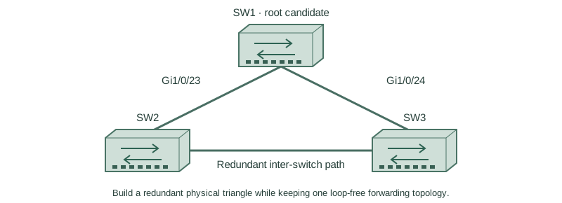
Build a redundant physical triangle while keeping one loop-free forwarding topology.
Independent lab examples; selected output and frame summaries are illustrative. Port naming and command support vary by switch and software release.
Network and objective
Classic PVST+ is used to expose original STP behavior; rapid-PVST+ and MST are separate lessons.
Use three fresh isolated switches with Gigabit trunks: SW1 Gi1/0/23 ↔ SW2 Gi1/0/23; SW1 Gi1/0/24 ↔ SW3 Gi1/0/24; SW2 Gi1/0/24 ↔ SW3 Gi1/0/23. Both VLANs10/20 exist on every switch. Baseline SW1/SW2/SW3 priorities are4096/8192/12288, with short costs and no extra links. Start independently from the included baseline for each lesson; subsequent repair snippets apply to the named device.
How it works
Ethernet broadcasts and unknown-unicast copies have no link-layer hop limit. A forwarding loop can repeatedly replicate frames and move learned source locations. Redundant physical links therefore need a loop-control design before connection, not after a storm starts.
BPDUs advertise a root bridge and path information. The lowest bridge ID wins root election. Each non-root switch chooses a root port; a designated port serves each segment. An alternate path blocks ordinary data while preserving a standby route. A blocked port can still process control information.
Configure or inspect
SW1
vlan 10
vlan 20
spanning-tree mode pvst
spanning-tree pathcost method short
spanning-tree vlan 10 priority 4096
spanning-tree vlan 20 priority 4096
interface range GigabitEthernet1/0/23 - 24
 switchport mode trunk
 switchport trunk allowed vlan 10,20
 switchport nonegotiate
 no shutdown
exit
SW2
vlan 10
vlan 20
spanning-tree mode pvst
spanning-tree pathcost method short
spanning-tree vlan 10 priority 8192
spanning-tree vlan 20 priority 8192
interface range GigabitEthernet1/0/23 - 24
 switchport mode trunk
 switchport trunk allowed vlan 10,20
 switchport nonegotiate
 no shutdown
exit
SW3
vlan 10
vlan 20
spanning-tree mode pvst
spanning-tree pathcost method short
spanning-tree vlan 10 priority 12288
spanning-tree vlan 20 priority 12288
interface range GigabitEthernet1/0/23 - 24
 switchport mode trunk
 switchport trunk allowed vlan 10,20
 switchport nonegotiate
 no shutdown
exit
Verify the result
SW3#show spanning-tree vlan 10
VLAN0010
  Spanning tree enabled protocol ieee
  Root ID Priority 4106
          Address 0200.0000.0001
  Bridge ID Priority 12298
Interface           Role Sts Cost  Prio.Nbr Type
Gi1/0/24            Root FWD 4     128.24   P2p
Gi1/0/23            Altn BLK 4     128.23   P2p
SW1 is the intended root. SW3’s direct Gi1/0/24 path costs4, while the path through SW2 costs8. Gi1/0/23 remains alternate, so both physical paths exist without both forwarding VLAN10 data.
Failure and recovery
If all three links forward after disabling STP or filtering BPDUs, do not keep sending test broadcasts. Isolate the redundant path, restore the intended protocol and verify roles before reconnecting.
SW3
interface GigabitEthernet1/0/23
 shutdown
exit
spanning-tree mode pvst
interface GigabitEthernet1/0/23
 no shutdown
Further reading
Key Takeaways
- Physical redundancy and data forwarding are different.
- STP uses BPDUs to choose loop-free roles.
- The lowest bridge ID wins root election.
- Non-root switches select one root port per instance.
- An alternate port preserves standby connectivity.