Root bridge placement
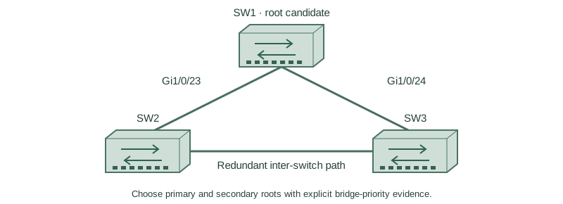
Choose primary and secondary roots with explicit bridge-priority evidence.
Independent lab examples; selected output and frame summaries are illustrative. Port naming and command support vary by switch and software release.
Network and objective
Classic PVST+ is used to expose original STP behavior; rapid-PVST+ and MST are separate lessons.
Use three fresh isolated switches with Gigabit trunks: SW1 Gi1/0/23 ↔ SW2 Gi1/0/23; SW1 Gi1/0/24 ↔ SW3 Gi1/0/24; SW2 Gi1/0/24 ↔ SW3 Gi1/0/23. Both VLANs10/20 exist on every switch. Baseline SW1/SW2/SW3 priorities are4096/8192/12288, with short costs and no extra links. Start independently from the included baseline for each lesson; subsequent repair snippets apply to the named device.
How it works
A root should be placed where the topology and traffic policy intend, rather than left to the lowest factory MAC. A lower numerical priority is preferable. With the extended system ID, configured priorities use increments of4096 and displayed values include the VLAN identifier.
The root primary/secondary convenience commands select configuration values based on implementation and current observations; they are not permanent election locks. An even lower bridge ID can still win later. Explicit priorities make this lab’s intended hierarchy easy to audit.
Configure or inspect
SW1
vlan 10
vlan 20
spanning-tree mode pvst
spanning-tree pathcost method short
spanning-tree vlan 10 priority 4096
spanning-tree vlan 20 priority 4096
interface range GigabitEthernet1/0/23 - 24
 switchport mode trunk
 switchport trunk allowed vlan 10,20
 switchport nonegotiate
 no shutdown
exit
spanning-tree vlan 10 priority 4096
SW2
vlan 10
vlan 20
spanning-tree mode pvst
spanning-tree pathcost method short
spanning-tree vlan 10 priority 8192
spanning-tree vlan 20 priority 8192
interface range GigabitEthernet1/0/23 - 24
 switchport mode trunk
 switchport trunk allowed vlan 10,20
 switchport nonegotiate
 no shutdown
exit
spanning-tree vlan 10 priority 8192
SW3
vlan 10
vlan 20
spanning-tree mode pvst
spanning-tree pathcost method short
spanning-tree vlan 10 priority 12288
spanning-tree vlan 20 priority 12288
interface range GigabitEthernet1/0/23 - 24
 switchport mode trunk
 switchport trunk allowed vlan 10,20
 switchport nonegotiate
 no shutdown
exit
spanning-tree vlan 10 priority 12288
Verify the result
SW1#show spanning-tree vlan 10
Root ID    Priority 4106
           Address 0200.0000.0001
           This bridge is the root
SW2#show spanning-tree vlan 10
Root ID    Priority 4106
Bridge ID  Priority 8202
SW1’s configured4096 becomes4106 forVLAN10. SW2 is the planned secondary, not currently the root. Verify the same root identity from the other switches.
Failure and recovery
An unexpected lower-priority bridge can win if the boundary permits it. Repair root placement and use root guard on designated downstream boundaries where receiving a superior claim is prohibited by design.
Restore approved bridge priorities and verify the root from multiple switches. Apply boundary protections deliberately rather than assuming a primary keyword locks election.
Further reading
Key Takeaways
- Lower numerical bridge priority is preferred.
- Displayed priority includes the VLAN ID.
- Supported increments commonly use4096.
- Primary/secondary macros are not permanent locks.
- Verify root identity from multiple points.