Introduction to LAN
Identify the local network, the switch that joins its devices, and the routed boundary to remote networks.
Independent lab examples; selected output and frame summaries are illustrative. Port naming and command support vary by switch and software release.
Start with a local conversation
H1 needs to exchange files with H2 in the same office. Their Ethernet interfaces attach to SW1, and both hosts use the same IPv4 subnet. The switch joins those local links. The Internet connection is not needed for this local exchange: a failed provider link need not prevent two healthy local hosts from communicating.
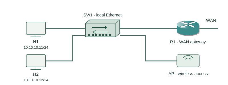
Separate the device roles
| Component | Role in this network |
|---|---|
| Switch | Connects Ethernet segments and forwards frames within a VLAN. |
| Access point | Bridges wireless clients into the local network under its configured access policy. |
| Router | Forwards IP traffic between IP networks, including the WAN boundary. |
| Host | Generates and receives application traffic using its network interface. |
One physical home gateway can combine switching, routing and wireless functions. Those remain different roles even when the hardware is a single box. A managed switch may have an IP address for administration; hosts do not need the switch to have an IP address merely to forward ordinary Layer 2 frames.
Scale from an office to a campus
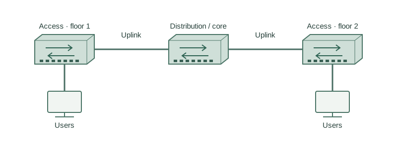
A LAN may cover one room, a building or a nearby campus. Access switches provide edge ports; an aggregation or distribution layer joins access blocks. Larger designs can add a separate core. These names describe roles, not a mandatory number of boxes.
Redundant links need a deliberate loop-prevention or aggregation design. Do not add an extra cable between switches and assume Ethernet will safely choose a path. Spanning tree and link aggregation are later topics.
Build one isolated access segment
Use a fresh lab switch with three suitable Ethernet access ports and no production connections. Connect H1–H3 as below. Assign these addresses and the listed locally administered MAC addresses in the host or hypervisor settings if supported; otherwise record the actual MAC values and use those in observations. No default gateway is required for this same-subnet exercise.
| Host | IPv4 address | Example MAC | SW1 port |
|---|---|---|---|
| H1 | 10.10.10.11/24 | 0200.0000.0011 | Gi1/0/1 |
| H2 | 10.10.10.12/24 | 0200.0000.0012 | Gi1/0/2 |
| H3 | 10.10.10.13/24 | 0200.0000.0013 | Gi1/0/3 |
configure terminal
vlan 10
 name LAB
interface range GigabitEthernet1/0/1 - 3
 switchport mode access
 switchport access vlan 10
 no shutdown
end
The commands make the intended VLAN explicit instead of relying on an existing port assignment. Other switch state is assumed to be a clean lab baseline; do not paste this recipe into a live network.
Verify links, membership and local reachability
SW1#show interfaces status
Port      Name  Status       Vlan  Duplex  Speed  Type
Gi1/0/1         connected    10    a-full  a-1000 10/100/1000BaseTX
Gi1/0/2         connected    10    a-full  a-1000 10/100/1000BaseTX
Gi1/0/3         connected    10    a-full  a-1000 10/100/1000BaseTX
Each intended port is connected and assigned to VLAN 10. A link being up does not prove the host address or application is correct.
H1$ ping -c 3 10.10.10.12
3 packets transmitted, 3 received, 0% packet loss
This Linux-host example tests H1–H2 IP reachability without crossing R1. If it fails, check host addressing and firewall policy as well as cables, port state and VLAN membership. Ping success does not measure every application or forwarding condition.
Further reading
Key Takeaways
- A local switched conversation does not inherently depend on Internet service.
- Switches, access points and routers perform different roles.
- A campus can contain multiple access blocks joined through distribution or core switches.
- An IP management address is not a prerequisite for basic Layer 2 frame forwarding.
- Verify physical links, VLAN membership and host configuration separately.