CEF forwarding
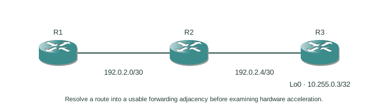
Resolve a route into a usable forwarding adjacency before examining hardware acceleration.
Independent lab examples; selected output and frame summaries are illustrative. Port naming and command support vary by switch and software release.
Network and objective
CEF is a platform forwarding architecture. Its tables can exist in software; hardware offload and exception handling depend on the device.
R1–R2–R3 form a routed chain. R1–R2 uses 192.0.2.0/30 (.1/.2); R2–R3 uses 192.0.2.4/30 (.5/.6); R3 owns 10.255.0.3/32. Configure the corresponding interfaces and reverse routes on R2/R3 before testing.
How it works
A routing-table path can require recursive next-hop resolution. R1’s destination route points to 192.0.2.6, and a second route resolves that address through adjacent R2 at 192.0.2.2. The FIB represents destination forwarding; an adjacency supplies the link-layer rewrite toward the adjacent neighbor.
Routed IPv4 forwarding replaces the Ethernet addresses, decrements TTL and updates the IPv4 header checksum. Ordinary bridging within a VLAN does not decrement IP TTL. Control-plane protocols and some exceptions need separate processing; CEF does not promise that every packet stays out of the CPU.
Configure or inspect
R1
interface GigabitEthernet0/0
 ip address 192.0.2.1 255.255.255.252
 no shutdown
ip route 192.0.2.4 255.255.255.252 192.0.2.2
ip route 10.255.0.3 255.255.255.255 192.0.2.6
R2
interface GigabitEthernet0/0
 ip address 192.0.2.2 255.255.255.252
 no shutdown
interface GigabitEthernet0/1
 ip address 192.0.2.5 255.255.255.252
 no shutdown
ip route 10.255.0.3 255.255.255.255 192.0.2.6
R3
interface GigabitEthernet0/0
 ip address 192.0.2.6 255.255.255.252
 no shutdown
interface Loopback0
 ip address 10.255.0.3 255.255.255.255
ip route 192.0.2.0 255.255.255.252 192.0.2.5
Verify the result
R1#show ip cef 10.255.0.3
10.255.0.3/32
  recursive via 192.0.2.6
    nexthop 192.0.2.2 GigabitEthernet0/0
R1#show adjacency GigabitEthernet0/0 detail
Protocol Interface                 Address
IP       GigabitEthernet0/0         192.0.2.2
         0200000000020200000000010800
The final Ethernet neighbor is R2, even though the configured recursive next hop names R3. The displayed rewrite contains destination/source MAC and EtherType, not the entire future packet.
Failure and recovery
If the neighbor cannot be resolved, a destination FIB entry does not guarantee delivery. Verify R1–R2 link/IP/ARP and R2’s onward route, then retest the destination and reverse path.
Restore the adjacent link or address-resolution failure first. Do not disable CEF to hide an unresolved next hop.
Further reading
Key Takeaways
- RIB, FIB and adjacency state answer different questions.
- Recursive resolution ends at a usable adjacent next hop.
- A routed hop rewrites Ethernet encapsulation.
- IPv4 TTL decreases on routing, not ordinary bridging.
- CEF does not guarantee universal hardware offload.