Q-in-Q tunneling
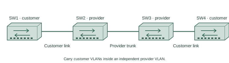
Carry customer VLANs inside an independent provider VLAN.
Independent lab examples; selected output and frame summaries are illustrative. Port naming and command support vary by switch and software release.
Network and objective
Requires a platform supporting 802.1Q tunneling and the required stacked-frame size; service-tag TPID and MTU commands vary.
SW1 and SW4 are customer switches; SW2 and SW3 are provider edges. SW1–SW2 and SW3–SW4 use customer-facing Gi1/0/1; provider SW2–SW3 uses Gi1/0/24. Customer VLANs 10/20 travel inside service VLAN 100.
How it works
The ingress provider edge adds a service tag while retaining the customer’s original tag. The far provider edge removes its service tag and delivers the customer frame. The provider forwards using service context rather than merging all customers’ inner VLAN numbering.
Treat the customer-facing tunnel port and provider-facing trunk as different roles. Account for the extra four bytes throughout the provider path, using the exact platform’s frame-size definition. Layer 2 control protocols may require explicit tunneling support and policy; data encapsulation alone does not guarantee transparent STP or LACP transport.
Configure or inspect
vlan 100
interface GigabitEthernet1/0/1
 switchport access vlan 100
 switchport mode dot1q-tunnel
 no shutdown
interface GigabitEthernet1/0/24
 switchport mode trunk
 switchport trunk allowed vlan 100
 no shutdown
Verify the result
SW2#show interfaces GigabitEthernet1/0/1 switchport
Administrative Mode: dot1q-tunnel
Operational Mode: dot1q-tunnel
Access Mode VLAN: 100
Illustrative provider frame:
  Service VID 100 / Customer VID 10 / IPv4 payload
Mirror the edge configuration on SW3. Customer SW1/SW4 use trunks permitting 10,20 toward their provider. Verify small and near-MTU customer traffic; a small ping cannot prove stacked-frame capacity.
Failure and recovery
Small frames pass but larger customer frames fail when an intermediate provider port cannot accept the added encapsulation. Check supported MTU semantics and every hop instead of changing customer VLAN IDs.
Apply the documented provider frame-size setting and its activation requirements in a maintenance lab; then validate the largest intended customer frame in both directions.
Further reading
Key Takeaways
- Provider and customer VLAN IDs have separate roles.
- The inner tag is preserved through the service.
- Tunnel ports and trunks have different responsibilities.
- The added tag needs end-to-end size support.
- Control-protocol tunneling is an explicit separate decision.