Switch virtualization concepts
Distinguish one logical switch from two independent switches with redundant links.
Independent lab examples; selected output and frame summaries are illustrative. Port naming and command support vary by switch and software release.
Network and objective
Conceptual comparison of stacking and chassis virtualization; technologies and limits are platform-specific.
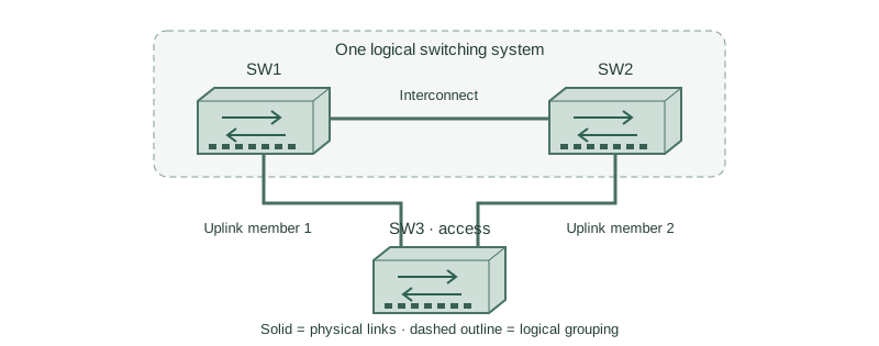
An access switch SW3 has one uplink to SW1 and one to SW2. Before virtualization SW1 and SW2 are separate bridge and control-plane identities; after a supported pairing they act as one logical neighbor.
How it works
A normal EtherChannel must terminate on one logical partner. Connecting one member to each unrelated switch does not create a valid aggregate. A stack or supported virtual chassis supplies a coordinated identity that permits a cross-member channel.
The physical boxes still have local interfaces, power, and forwarding resources. An active control plane manages the logical system; standby state and distributed forwarding behavior depend on the technology. One logical switch does not imply one physical failure domain disappears.
Distinguish a shared-control-plane design from multi-chassis link aggregation with separate control planes. Both can present a useful aggregation partner, but their synchronization, configuration, and split-brain behavior differ.
Configure or inspect
No feature change is required for this conceptual comparison. Inspect the operational state below on an isolated compatible lab platform.
Verify the result
Design comparison (conceptual)
Before: SW3 -> SW1 and SW2, independent LACP identities
After:  SW3 -> logical pair, coordinated LACP identity
Failure checks: member, interconnect, control plane, power
The useful evidence is a common logical identity and the correct failure behavior. Two chassis listed in inventory alone does not establish that the system is ready for cross-chassis forwarding.
Failure and recovery
The access-switch bundle is connected to two standalone switches. Matching the port-channel number on all three devices does not make the remote switches one system.
Restore independent links with spanning tree while the design is corrected, or deploy a supported stack/virtual-chassis solution and verify its interconnect and recovery mechanisms before forming the multi-chassis bundle.
Further reading
Key Takeaways
- One logical partner is required for a normal aggregate.
- Physical and logical redundancy are different.
- Stacks need a supported interconnect.
- Split-brain handling is part of the design.
- Platform names do not imply identical behavior.